Control Frames#
The skplatform package uses the following coordinate systems during its analysis
Instrument Control Frame (ICF)
Laboratory Control Frame (LCF)
Platform Control Frame (PCF)
Geodetic Control Frame (GCF)
Geographic Geocentric (ECEF)
Instruments coordinates are defined in the Instrument Control Frame with \(\hat{x}\) along the optical-axis or boresight of the instrument. Fields of view and lines of sight emanating from the instrument are canonically described in this coordinate frame. The goals of the transforms are,
Convert unit vectors from the instrument control frame to the geographic geocentric control frame for easy use by radiative transfer code.
Provide methods to orient the instrument so it is looking at specific points on the Earth’s surface or atmosphere.
The instrument is mounted on a platform and by default the instrument’s optical axis is aligned with the platform’s \(\hat{x}\) unit vector, which is often the forward direction but can be arbitrary. The instrument’s mounting orientation on the platform is changed by setting the instrument’s azimuth, elevation and roll.
The platform is initially configured so its forward unit vector, \(\hat{x}\), is looking North, regardless of location. The platform can be rotated to point in other directions by setting its yaw, pitch and roll. Simulator code may avoid setting yaw, pitch and roll directly and instead invoke helper functions to set them so the instrument is looking towards a specific point on the Earth’s surface or atmosphere.
The platform pointing coordinates are converted from geodetic coordinates to geographic-geocentric coordinates once the platform’s location in space is determined by specifying latitude, longitude and height.
Processing#

The attitude solution flows via a set of rotation matrices from look vectors expressed in the Instrument Control Frame to the same look vectors expressed in global ECEF unit vectors.
Step |
Description |
Target Matrix |
Simulations |
Instruments |
|---|---|---|---|---|
1 |
Define look vectors in the Instrument Control Frame |
Optional |
Recommended |
|
2 |
Initialize ICF to be co-aligned with LCF. |
\(R_{LCF} = I\) |
Implicit |
Implicit |
3 |
Mount instrument in Lab Control Frame, set azimuth, elevation |
\(R_{LCF}\) |
Optional |
Recommended |
4 |
Flip LCF to co-align with PCF |
Implicit |
Implicit |
|
5 |
Initialize PCF to be co-aligned with GCF |
\(R_{PCF} = I\) |
Implicit |
Implicit |
6 |
Rotate platform with yaw, pitch roll, algorithms etc. |
\(R_{PCF}\) |
Yes |
Yaw, Pitch, Roll |
7 |
Set Location of platform to lock GCF to global coords |
Yes |
Yes |
|
8 |
Rotate local GCF coords to global ECEF coords |
Yes |
Yes |
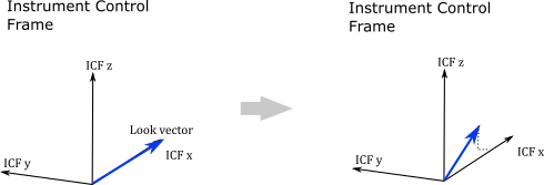
Fig. 5 Look vectors are defined within the ICF frame.#
Step 1: Define look vectors in ICF#
The ICFx axis is defined as the nominal boresight of the instrument while the ICFy and ICFz are usually parallel to the detector image plane axes. By default, the system is created with one look vector parallel to the ICFx axis but this can be changed the user to be either a single look vector or an array of look vectors.
The look vectors usually represent lines of sight associated with specific locations on the detector image plane (eg pixels). The look vectors are expressed in terms of the ICF unit vectors.
Step 2: Mount the ICF in the Laboratory Control Frame#
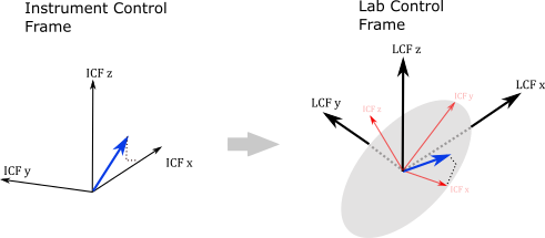
Fig. 6 The entire ICF frame and look vectors are intrinsically rotated to the lab control frame.#
Right-handed intrinsic rotations are applied to the Instrument Control Frame and look vectors. This rotation represents mounting an instrument on an aircraft, gondola or laboratory table where the whole instrument is physically rotated with respect to the axes used in the lab, aircraft, gondola. After transformation the look vectors are expressed in LCF coordinates.
By default the Labortaory Control Frame and the Instrument control frame are co-aligned, implying its has no action unless rotation matrices are actively set . The laboratory control frame is typically used by real instruments in real experiments but is ignored by most simulation code.
Step 3: Flip the LCF to the Platform Control Frame#
We provide an intermediate intrinsic rotational transform where look vectors expressed in the lab control frame are transformed to the platform control frame by rolling 180 degrees around LCFx. The platform control frame has a coordinate system similar to aircraft, where the X is in the forward direction, Y axis is to starboard and the Z axis is downward.
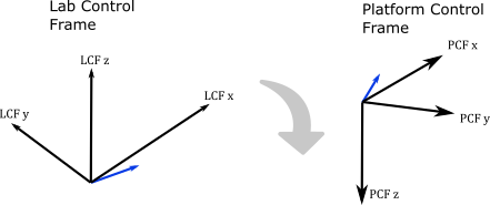
Fig. 7 Flip the laboratory control frame to the platform control frame. Roll 180 degrees around LCFx.#
The platform control frame is used by both real instruments and by simulation code. Real instruments will typically provide time series of the yaw, pitch and roll provided by the platform (spacecraft, aircraft, gondola etc.) while simulations use various methods and techniques to orient the platform so the instrument is looking at a specific target.
By default the Platform Control Frame is co-aligned with local geodetic coordinates:
PCFx is pointing due North
PCFy is pointing due East
PCFz is pointing straight down.
Step 4: Rotate PCF with yaw, pitch, roll#
Instrument Control Frame (ICF)#
The Instrument Control Frame (ICF) specifies a 3 axis right-handed system that is fixed to the instrument. Lines of sight and field of views are defined in this control frame. These entities are typically rotated into the platform control frame and from there rotated to look at a given target point.

The \(\hat{x}\) unit vector of the ICF is arranaged so it parallel to the nominal optic axis or boresight of the instrument and points away from the instrument. The \(\hat{y}\) and \(\hat{z}\) unit vectors are in the plane of the entrance aperture and \(\hat{z}\) is placed so it has an upwards component when the instrument is sitting on a table in a lab. The \(\hat{y}\) is chosen to form the third axis of a right-handed system but is often placed so it is horizontal.
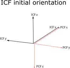
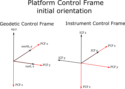
The instrument control frame is initialized so it is aligned upwards with resepect to the platform control frame with the boresight of the instrument \(\hat{x}_{ICF}\) parallel to \(\hat{x}_{PCF}\). The respective \(\hat{y}\) and \(\hat{z}\) unit vectors are anti-parallel.
All rotations, typically azimuth and elevation, that are applied to place the instrument into its mounted position in the platform control frame should start by assuming the instrument control frame is in its initial orientation with respect to the platform control frame.
Lab Control Frame (LCF)#
The Laboratory Control Frame (ICF) specifies a 3 axis right-handed system used to represent a laboratory environment. This will typically represent an actual lab environment or a gondola, aircraft of spacecraft mounting platform. It can also be used to account for steering mirror movement within the instrument.
The lab control frame is initialized so it is aligned upwards with resepect to the platform control frame with the boresight of the instrument \(\hat{x}_{ICF}\) parallel to \(\hat{x}_{LCF}\). The respective \(\hat{y}\) and \(\hat{z}\) unit vectors are parallel.
Platform Control Frame (PCF)#
The Platform Control Frame (PCF) specifies the coordinate system used by the platform that the instrument is mounted too. Typical platforms are satellites, aircraft, gondola as well as observatories on the ground. Platforms will define a 3 axis right-handed system. For aircraft the \(\hat{x}\) is parallel to the body of the plane and points forward, \(\hat{z}\) is perpendicular to the body and wings and points downward when the plane is flying level, \(\hat{y}\) is parallel to the wings and points to the startboard side. Satellites and balloon gondolas may choose other ways to specify the 3 axis system but keep in mind that all rotations are right-handed and using other coordinate systems, where \(\hat{z}\) is up for example, may generate counter-intuitive rotations when using yaw, pitch, azimuth or elevation.
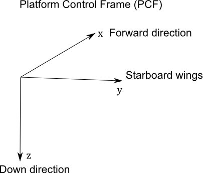
All platforms are able to express the 3 unit vectors in terms of local geodetic coordinates (west,south up) or geographic geocentric coordinates.
The Platform Control Frame is initialized so \(\hat{x}_{PCF}\) is co-aligned with local North, \(\hat{y}_{PCF}\) is pointing East and \(\hat{z}_{PCF}\) is pointing downwards.
Geodetic Control Frame (GCF)#
The geodetic control frame is a 3 axis right-handed system defined at any location by the geodetic latitude and longitude.
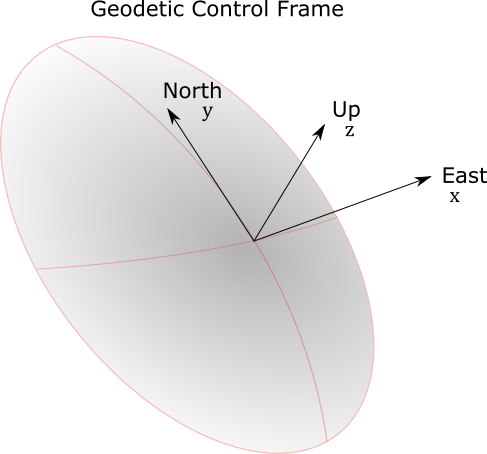
The \(\hat{x}\) is given by local east, \(\hat{y}\) is given by local north and \(\hat{z}\) is given by local up. This coordinate system is based upon an oblate spheroid geoid where \(\hat{z}\) is perpendicular to the surface of the oblate spheroid and does not usually pass through the center of the Earth.
Geocentric Control Frame (ECEF)#
The geocentric control frame is a geographic coordinate system with its origin at the centre of the (oblate spheroid) Earth. The system is synonomous with the ITRF system using the WGS84 reference sphere. The \(\hat{z}\) is parallel to the rotation axis of Earth and points from the center through the North pole. The \(\hat{x}\) points in the plane of the equator from the center of the Earth to the Greenwich meridian (in the Atlantic ocean just off the cosat of Africa). The \(\hat{y}\) forms the third axis of a right-handed system and points from the center in the plane of the equator to the 90E meridian (in the Indian ocean west of Sumatra). The system rotates with the Earth.