Introduction
Skimpy is a python package that assists users to model atmospheric radiance incident upon optical instrument’s studying the Earth’s atmosphere. The library is focussed on accounting for instrument characteristics and their impact upon signals measured by an instrument. It has application as a simulator when designing instruments and as a forward model when performing data analysis.
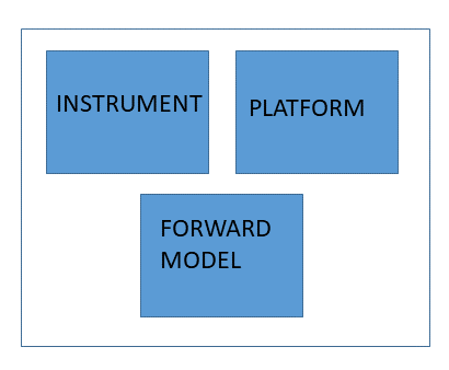
The library has the following key components:
- Instrument. The API provides mechanisms to describe fields of view and wavelength ranges in the front end of an instrument. The instrumenT interfaces with Platform and Forward Model to calculate radiances at the front aperture of the instrument and propagates the radiance through the instrument to the detector pixels in the back end of the instrument. The code provides the ability to sub-divide each field of view into smaller segments permitting high resolution studies. UVIS-NIR calculations can also utilize a hybrid wavelength mode where a relatively coarse wavelength grid is interpolated to a high resolution grid that matches the resolution of solar spectra stored inside sasktran.
- Platform. The API provides support for various platforms, spacecraft, planes, balloons and ground based stations. It defines several coordinate systems that, for example, allow an instrument to be mounted on a platform and to be rotated to look at target locations. Support for Kepler and SGP4 satellite orbit propagators are provided and includes simple sun-synchronous, molniya and geo-stationary orbits which are suitable for many simulation studies.
- Forward Model. The API provides methods to wrap the various radiative transfer models implemented in the Sasktran package. The code provides support for both UVIS-NIR and IR calculation.
Instrument
The Instrument component describes the optical instrument used in the skimpy package. Users either choose or develop instrument models specific to their needs. Each instrument model must inherit from the Instrument abstract base class.
The Instrument model subdivides all instruments into two parts: (i) a front-end component and (ii) a back-end component. The front-end component concerns itself with the radiance incident upon the front aperture of the instrument while the back-end is only concerned with how that incoming signal propagates through the instrument to the pixels on the back-end detector.
The business of calculating the radiances for the front-end component is common to all instruments and has extensive support within skimpy. On the other hand, the description of signals propagating through an instrument is specific to each instrument and has less support within skimpy. You can expect skimpy will calculate your front-end radiances without too much effort but if one of skimpy’s built in Instruments is too generic or not appropriate enough for your propagation needs then you will have to develop your own model.
Spectral Windows
The users interaction with the Instrument’s front-end aperture is primairly one of defining spectral windows suitable for their needs where a spectral window is the combination of one field of view with one range of wavelengths. It is important to choose the correct spectral windows for an instrument as this will have a big impact upon the flow of data through the skimpy system.
For example, the figure below shows a common scenario for a single slit spectrograph. There is a rectangular field of view in the front aperture that allows a range of wavelengths into the system. The single slit spectrograph collects light across a single field of view and disperses the incoming light by wavelength on to the detector plane.
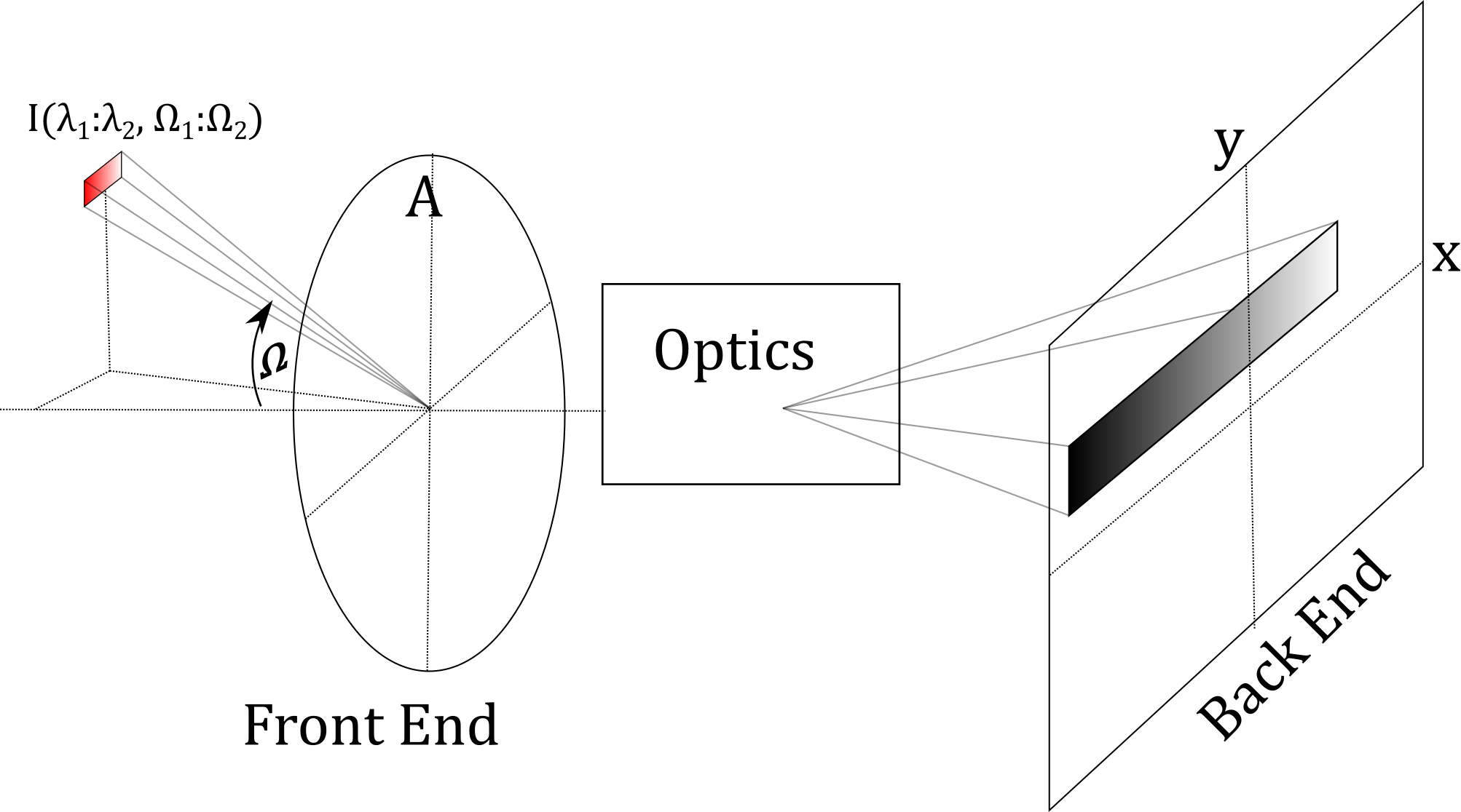
The instrument models used to propagate the radiances calculated at the front-end aperture to the back-end detector plane can be simple or complicatedd depending upon specific needs. For example, in the spectrograph above we could implement a very complex model that captures all the internal details of the instrument or we could implement a skimpy built in model that applies a point spread function to the wavelengths in the end optics of an instrument within a solid angle given by the field of view and a wavelength range given by the spectral point spread function. This combination of field of view and spectral point spread function are used to create the concept of an instrument pixel: pixels detect all the light across their field of view and spectral point spread function; the task at hand is to accurately calculate the distribution of light across the given solid angle and wavelength range. Skimpy allows an instrument to define as many fields of view and spectral point spread functions as required. The user then combine these items to create a list of pixels which form a realistic instrument model. For example:
- A single slit spectrograph can create an array of pixels, one for each wavelength on the detector plane. Each pixel can use the same single, common field of view but employ a unique instance of the spectral point spread function with the central wavelength made to match the wavelength on the detector plane. Variations in spectral resolution across the detector plane are easily managed by programming each point spread function with the appropriate fwhm parameter.
- An imaging AOTF (tunable filter) instrument can create many fields of view corresponding to the different fields of view of rectangular areas in the image plane (real pixels maybe) and combine them with several spectral point spread functions to create an arrays of pixels, one imaging array for each wavelength band considered. The spectral resolution of the AOTF can change with chosen wavelength by changing the fwhm of the corresponding spectral point spread function. In practice, the number of rectangular areas may have to be limited to keep the computational burden reasonable.
Platform
The Platform is the system that carries the optical instrument and may be a spacecraft, balloon, aircraft or ground-based observatory. The Platform system provides two primary functions
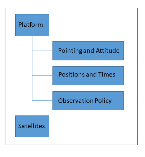
- it provides instrument pointing and attitude functions
- it provides capability via an observation policy to store where, when and what to loook at in space and time.
the attitude functions are implemented as a sequence of rotational transforms through a series of coordinate frames, see Transformations and Control Frames. The rotation matrices provide considerable flexibility and can handle most common scenarios:
- the instrument can be mounted on the platform at an arbitrary angle, useful for modelling measurements collected by a real instrument on a real platform.
- the system can properly handle the left-handed yaw-pitch-roll coordinate systems provided by many aircraft and balloons.
- the system can calculate the necessary platform rotations for an instrument to look towards a certain target, e.g.tangent altitude or ground locatio, which is useful for simulation work.
The second major component of the Platform system provides an observation policy that stores the time, position and look directions for each sample that will be calculated in the call to the radiative transfer model. The mehod of implementation is relatively straight forward. The position, time and pointing of the Platform object is manipulated by the user to be in one of the states required for the next radiative transfer calculation. The user then instructs the Platform object to capture its current state and add it to an internal list of cached states. This list of cached states, internally refered to as the observation policy, is queried by the Forward Model during a radiative transfer calculation..
The Skimpy package provides additional classes to support the implementation and realization of actual platform classes. We currently have SatelliteBase classes that can be used to simulate various orbits, for example,
- Kepler based orbits. These are simple orbits Kepler orbit with no forces other than the Earths gravity representes as a central point source.
- SGP4 satellite propagator using two line elements.
- Sun synchronous orbit simulator using the SGP4 satellite propagation model. Properly models the sun synchronicity as it includes gravitational forces upto and including J4. It does not include any atmospheric drag so this model is only appropriate for shorter durations (eg a few days).
- Molniya orbit using Kepler or SGP4 orbit propagators
- Simple geostationary orbits that stay rooted over a fixed location.
Users who wish to implement ground based locations do not need to use any additional software. This functionality is implicitly built into the Platform class. Similar statements can be applied to aircraft and balloons. The user is responsible for finding the location of the aircraft or ballon as well as the yaw pitch and roll but after this point they are directly supported by the Platform class.
Forward Model
The Forward Model is the Skimpy component that performs radiative transfer calculations. It is implemented as a shallow wrapper around the Sasktran radiative transfer engines. The type of sasktran engine is chosen when the Forward Model is created.
Radiative transfer calculations when its method calculate_radiance() is called at which point the
following steps are performed.
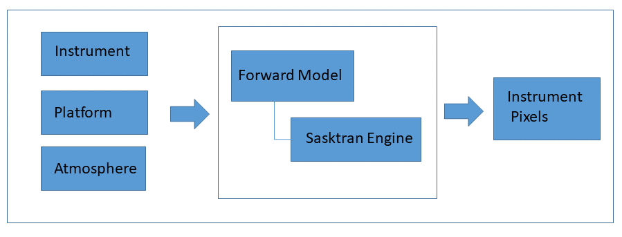
- The instrument and platform are queried to obtain a complete list of wavelengths and lines of sight.
- The Sasktran engine is created with suitable options and the atmosphere passed in by the caller. Appropriate radiances are calculated.
- The radiances are un-packed, processed and stored withith the pixels inside the instrument.
Skimpy typically uses the default settings of the sasktran engines which is adequate for most users settings while options are provided that allow fine-tuning of the sasktran engine parameters.